Just a note that the Garden sensor project has been updated.
Month: June 2017
New breakout boards – EFM8SB2
Created some new breakout boards to go with the EFM8SB2 chip I’ve been enjoying. One thing that is always a pain is the fact it is a surface mount board, so prototyping with a breadboard doesn’t exactly work very well. While using the 32 QFP chip is easier to hand solder, I was successfully soldering the tinier QFP24. While I was feeling confident that I can solder them, I created some breakout boards. While some generic boards from Schmartboards may work for this, I didn’t much appreciate their cost. 1 board from Schmartboards for a QFN board is around $6 each board. Ordering my own through Osh Park comes out to $0.89 per board for the most expensive one. So, easy choice. I happen to enjoy designing in KiCad as well so it works.
EFM8SB2 Breakout – 500mils, 24 pins.
First I designed just a breakout for the chip (EFM8SB2-24). I chose to go with the Castellations method to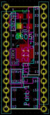 try and keep the footprint small. The board was $2.20 for an order of 3, which is $0.74 per board. The board is pretty much no frills. It has pads for the two suggested capacitors on top and one pad on the bottom for a 10k pull-up resistor on the C2CK line for programming. If one is going to surface mount the board, then that 10k resistor will need to be external, but otherwise normal pin-through leads can be soldered to it. The pads in the corners are much smaller, but I think it will hold. I’ll be testing it once my digi-key order comes in with the leads for this and for the surface mount leads I will use in the other boards. The board was designed for 0805 components. The pads may be large enough to accommodate 1205/6 components, but I would need to test.
The board will need testing, but it looks good and I think it should work well. One thing I want to change on future boards


is to spell out the port name along with the pin number. There wasn’t space to do that for all of the pins, but maybe pin numbers on one side and port number on the other would work. Then I could choose which side I want to have in the up position. Pins are standard breadboard spacing of 0.100 inches (100 mils) and 500 mils accross (5 pin spaces). While this was small and achieved multiple objectives, I wanted to make chips that are like normal DIP packages and only take 4 pin spaces across to bridge the middle of a bread board and no more. I will likely update the design to add the port names, verify the board works and then share it on Osh Park.
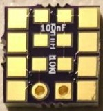
EFM8SB2 Breakout – 400mils, 8(10) pins.
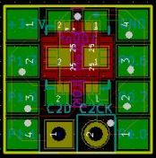
After designing and ordering the first board above, I was looking at the AVR tiny series. I was debating learning the AVR systems as a lot of support is out there for them.
I decided the end design of any of them isn’t too different then the EFM8 chips I have, except I already have a programmer for the EFM8’s and not the AVR chips. I liked the tiny footprint though and the ability to get a DIP package and drop it in a bread board. Some projects just don’t need that many GPIO pins. A recent project I did for an RGB stand only needed 6 GPIO pins, which something like this would work well. But the only packages for EFM8 chips are QFP and QFN. Well, re-enter the 24 pin QFN EFM8SB2. This is a limited design, expected to fit between the breadboard spacing and only have 4 pins each side. In order to make it that small, it is necessary to use SMT header pins. I was only able to find one type on Digi-key, and they seem pretty excessive in price, but they don’t seem to have any competitors so they can do that: Mill-Max 349 series. We will see how well they do. I should have the parts in on Thursday and can see if I am able to solder them on. Unfortunately the picture I took chopped off the top of this part. I will get another tonight. I have added the OshPark summary to flesh it out. The only note on this one is that I needed pins to program the chip, so added the C2D and C2CK pin locations in a non-dip manner. This would allow pins to be put in on top and allow programming without impacting the footprint in the breadboard. Support components are on the underside if desired – 10k pullup resistor for the C2CK line as will as the 2 suggested capacitors of 100nf and 1uF. My label for the 1uF capacitor didn’t come out and I will move labels around so it will work better. Unfortunately with the layout, I was not able to put the vias in for the bottom pad of the EFM8. This isn’t an issue too much if you use hot air, but hand soldering is an issue. I will be changing the layout some so that I can get a through hole or via grid in there.


EFM8SB2 Breakout – 400mils, 24 pins.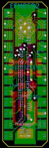
Last, but not least, I wanted to have a self contained unit. For the garden project, I will be using a Particle Photon for the Soil sensors and logging. I will be using an EFM8SB2-24 to manage the power. Taking readings from the 5 photoresistors and engaging the stepper motor to move the solar panel if needed. I liked how the Photon was mostly a self contained system and wondered if I could do that with the EFM8 on a single breadboard friendly design. I think I could have done better, but I don’t think this was too shabby of a design. I jokingly call this the medusa board for how the traces fan out from the EFM8.
Some adjustments I plan to make is that instead of tying the enable pin on the LDO to high, I would like to take that to a pad that the EFM8SB2 doesn’t need. Any of the ‘nc’ pads could be used, of which there are 3. That way the chip could be turned off and on at will. The design uses a TI TPS73633 which I have had good results with. It is a standard fixed LDO at 3.3V, but it is supposed to have an ultralow voltage drop allowing it to run off li-ion batteries nicely. I forgot to add in the low voltage cutoff chip, so I will need to either add that, or indeed breakout the enable pin so that li-ion batteries are not depleted too low. I have a 3.4V enable/disable chip available for this. This is just to help from over discharging the li-ion battery and maintaining long battery life. Lower than 3.4V and the LDO will have trouble delivering the 3.3V set for the output. Using the TPS73633 makes the input of the EFM8SB2 chip tolerant up to 6V, which will make it easier to interface with 5V systems. The output on the pins will still be at 3.3V, but it can at least be plugged in to a 5V system and not fry itself. The GPIO pins on an EFM8 are 5V tolerant as well, so it helps. I also will use one of the unused inputs to output the 3.3V to help simplify systems.


